Measurement and production of architectural floor plans, elevation and sectional drawings of existing buildings and structures. 3D scanning is now the standard method of measurement as It captures a highly accurate data set, which is reflected in the end user drawings.
We produce our drawings in-house as opposed to subcontracting which is common place especially for larger 3D projects. We have tried this and found on one project that the work was re subcontracted and split between technicians in different parts of the world. It may be cheaper, but it lacks oversight and accountability. The bare minimum is produced, whereas we are looking to hand over our best work every time.
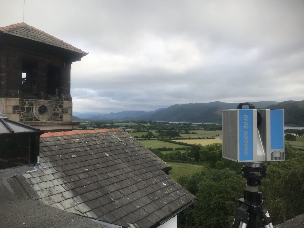
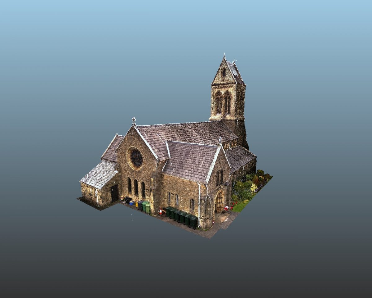
This phase shift scanner emits a laser light at alternating frequencies, measuring the difference between emitted and reflected signals to calculate distance. It can do this over a million times per second while also recording the angle and the intensity of reflection. Millions of XYZ points on intercepted surfaces are recorded and presented in greyscale. In comparison, a total station records 1 point at a time.
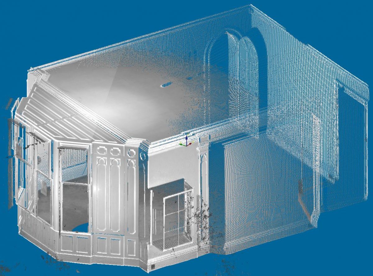
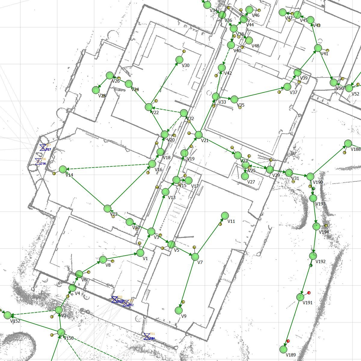
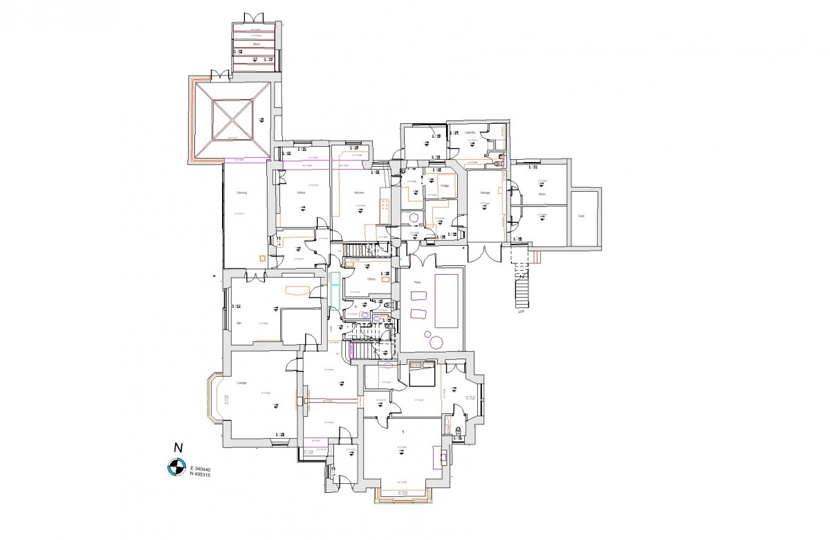
Chains of scans are linked / registered together and geolocated using external targets measured with a total station. The floor plan layout is visible in the point cloud slice, which we use to trace the walls. Software can determine the average width and best fit alignment of a straight wall length between two points.
The registered point cloud can be coloured with panoramic photography taken from the scans positions by matching the image pixels to the survey points.
Complex building footprints are drawn accurately. Software can square up and simplify these plans by distributing the angles. This is a standard procedure when working in 3D, Autodesk Revit especially. For 2D plans, we prefer to keep as close as possible to the site condition. This gives the end user confidence in inspecting dimensions.
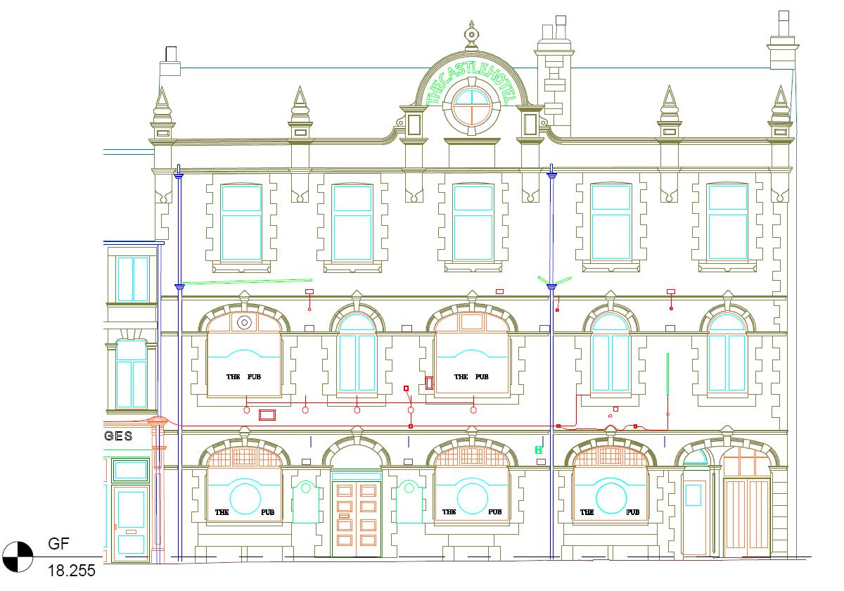
2D elevations can be drawn with high detail and accuracy. Literally, stone by stone. Again we prefer to draw “as is” so if the roof is wonky or the gable has a lean you will find this drawn. This takes a little longer, but in our view is preferable. The consultant is presented with the facts and can decide if further investigation is required.
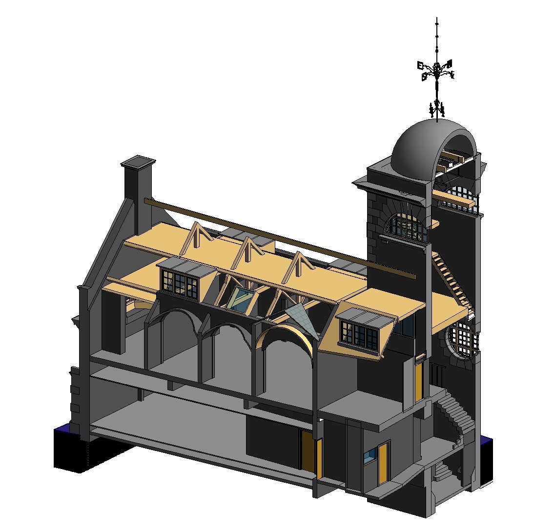
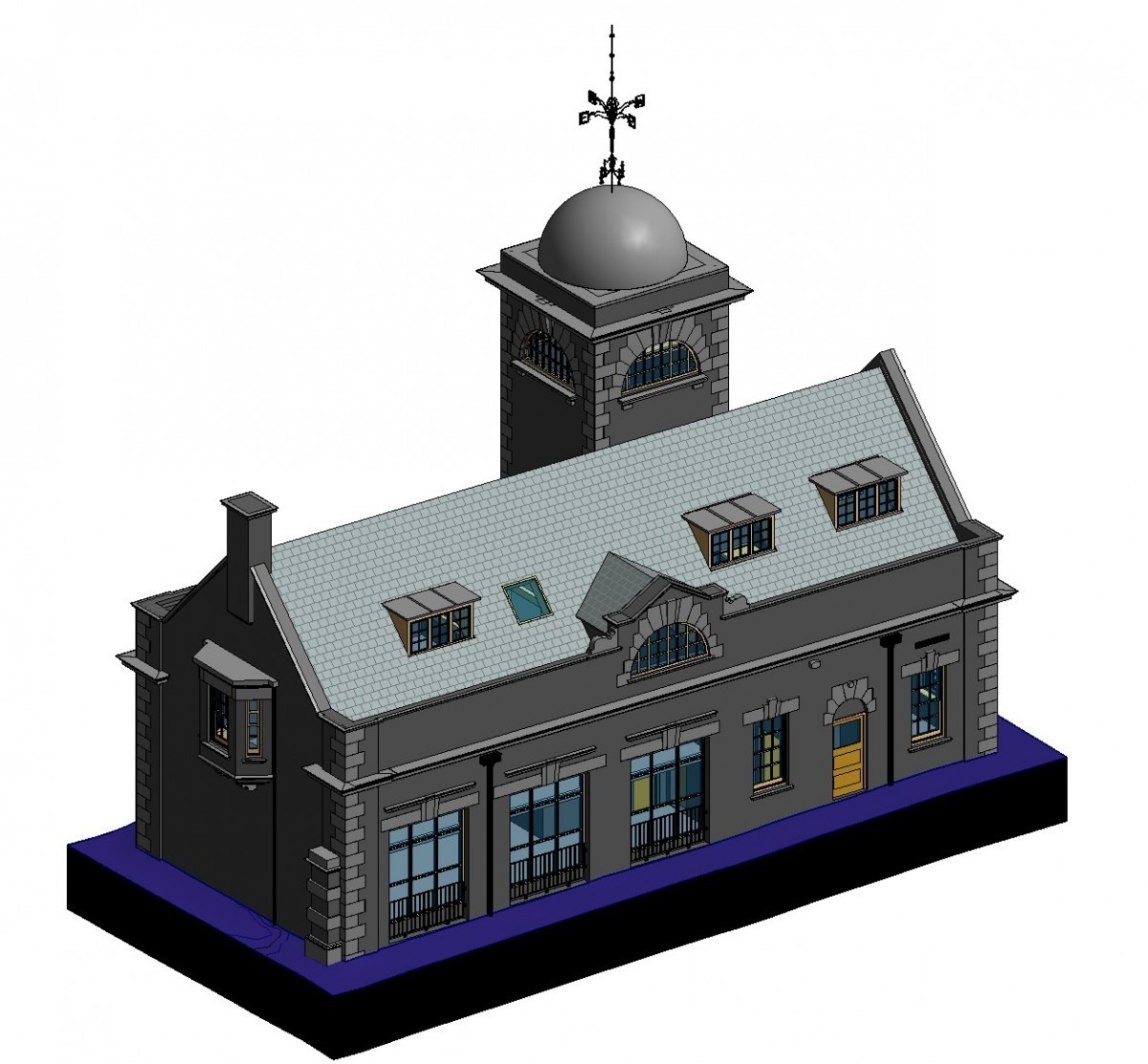
BIM, Building Information Models, produced in Autodesk Revit with FARO As-built plugin, are digital 3D models with a specified level of detail LOD 1 – 6. These are intended for better visuals and the long term maintenance of larger buildings.
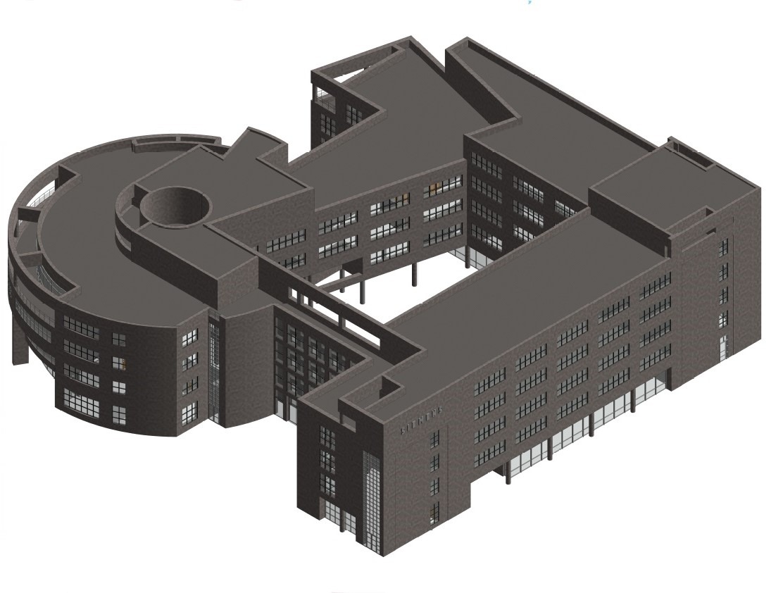
One advantage of working in 3D is being able to produce sections throughout the model.